
Introduction
Collimators are required to transform naturally diverging light-emission from an optical fiber to a parallel beam of light. Most fiber-optic collimators available are designed for thin fibers with low NA. High NA fibers such as Polymer Optical Fibers (POF) and Hard Polymer cladding fibers with an NA above 0.38 cannot be collimated efficiently by most of these standard products without a great reduction in output power (see Appendix for a discussion why special high NA collimators are required).
The Prizmatix FCM collimators are designed to work with High NA fibers and provide an efficient solution to this problem.
Please see Prizmatix’s wide range of Fiber-Coupled LED light sources .
Features
- Optimal performance using NA Aspheric Lenses
- High NA suited for High NA Polymer Optical Fibers (POF)
- Reciprocal SMA, FC or fiber connection
- Compact
Applications
- Spot illumination
- Component test and inspection
- Can be used in reverse direction as
a free-space to fiber coupler
Specifications:
- FCM1-06 - 0.63 NA
- FCM1-05 – 0.53 NA
- FCM05-05 – 0.53 NA
Fiber Connector: SMA or FC
Material: Black anodized aluminium
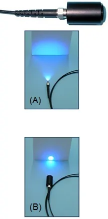
(A) Light output from fiber NA=0.5
(B,C) Same fiber with Collimator

The following table inbdicates the far field divergence angle of Prizmatix Collimators
for High NA fibers:
|
|
|
||||||||||||||||||||||||||||||||||||||||||||||||||||||||||||||||||||||||||||||||||||
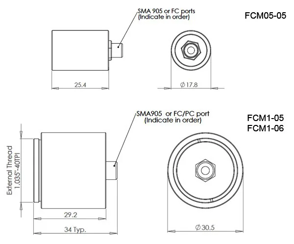
Dimensions
Appendix: Why special High NA collimators are required?
Light emits from multimode fibers as a wide cone of light. The divergence angle θmax is dictated by the reflection between the fiber's core and cladding, according to their refractive index, and is usually represented as the fiber's Numerical Aperture (NA). The general relation in air is:
NA= sin(θmax/2)
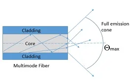
Fig. A1: Optical fiber emission cone of light
The following table compares the full emission angle (2θmax) of common NA fibers:
| Typical Fiber Type | NA | Full Emission Cone | |
| α[RAD] | α[Deg] | ||
| Silica Fiber | 0.22 | 0.44 | 25.4 |
| Polymer Optical Fiber (POF) | 0.5 | 1.05 | 60.0 |
| Polymer Optical Fiber (POF) | 0.6 | 1.29 | 73.7 |
| Polymer Optical Fiber (POF) | 0.63 | 1.36 | 78.1 |
| Liquid Light Guide (Prizmatix LLG-3 or LLG-5) | 0.6 | 1.29 | 73.7 |
| Prizmatix Optogenetics-Fiber-200 | 0.66 | 1.44 | 82.6 |
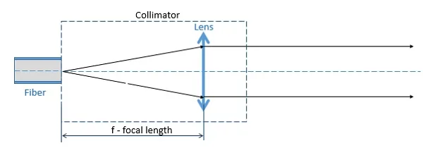
In collimator the fiber is placed at the focus of the collimator lens so the output rays will be parallel to the optical axis.
Standard collimators are designed for low NA fibers (like NA 0.22) therefore when high NA fiber is connected to such collimator the highly divergent rays will be lost (Fig. A3 (A)) resulting in significant power loses. Alternatively if high NA fiber will be connected to high NA collimator the collimator lens NA is matched to the NA of the fiber resulting in good power throughput (Fig.A3 (B)).
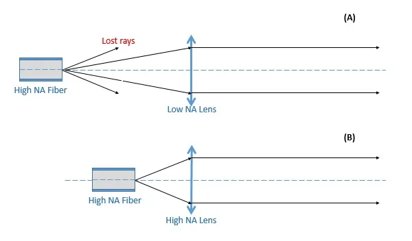
(B) High NA fiber connected to high NA Collimator Lens
The core diameter of the optical fiber will have significant effect on the far field divergence angle of the collimator output beam. As was shown above in collimator the optical fiber is placed at focal point of the lens. Fig. A4 shows the effect of non-infinitesimal radiant Object placed at focal point of the lens. As size of the Object (d) increasing the output beam divergence angle is increasing as well according to:
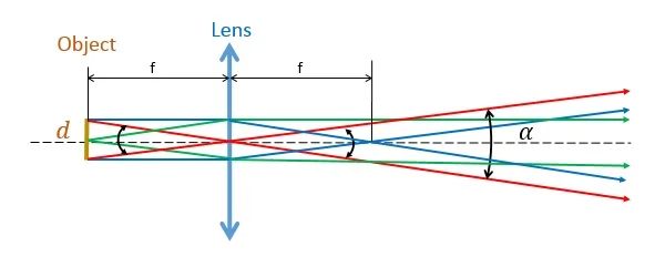
Effect of non-infinitesimal radiant Object placed at focal point of the lens. According to paraxial approximation: Rays divergent from focal point (in green) will travel parallel to optical axis after the lens, Rays traveling parallel to optical axis (in blue) will pass through the focal point on the right side, Rays passing through center of the lens (in red) will continue without refraction. The non-infinitesimal size of the object will cause the output rays to divergent at full angle α
Multimode high NA fibers are in most cases too large to be considered a point source. Hence, the beam leaving the collimator will not be of constant diameter, but slightly expanding. Smaller fibers will yield a small divergence angle, whereas large core fibers will generate a larger divergence angle. In order to reduce the output beam divergence of the collimator, longer focal length lenses are required along with maintaining high NA. If we need to satisfy these two requirements and still to reduce the beam divergence we will need to increase the lens diameter and consequently we will have an increase of output beam diameter as shown in Fig. A5
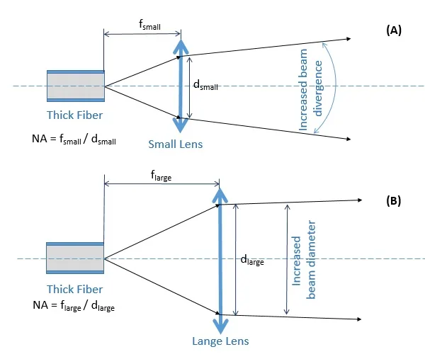
In order to reduce divergence angle of the collimator output beam, larger size lens with same NA as the optical fiber is required. This will result in increase of the output beam diameter. (A) Small size lens, (B) Large size lens. Both lenses have same NA.
© |